|
Custom design and manufacture of state-of-the-art
battery chargers, UPS, and power supplies for OEMs in a hurry?

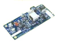
This is a microprocessor controlled DC/DC
converter which can be used as a solar charge controller for lithium-ion,
Nickel-Cadmium, and Nickel metal hydride batteries. It also has serial
communications and is programmable with great flexibility.
 Serial communications allows you
to control voltage, current, or power remotely, or to select on-board
programs. Serial communications allows you
to control voltage, current, or power remotely, or to select on-board
programs.
 Very flexible input and output
voltages available Very flexible input and output
voltages available
 Can be used as a solar charge
controller for a wide variety of cell counts and battery capacity. Can be used as a solar charge
controller for a wide variety of cell counts and battery capacity.
 Can use locally to the battery to
boost voltage after a long wire run, for example on POE. Can use locally to the battery to
boost voltage after a long wire run, for example on POE.
 Output voltage can be higher or
lower than the input voltage. Output voltage can be higher or
lower than the input voltage.
 State-of-the-art charging
algorithms available for a variety of battery chemistries and types State-of-the-art charging
algorithms available for a variety of battery chemistries and types
 Also useful in other energy
harvesting applications since it can be programmed to use whatever power is
available, unlike other battery charging circuits. Also useful in other energy
harvesting applications since it can be programmed to use whatever power is
available, unlike other battery charging circuits.
 Input and output voltage and current sense can be read by the
on-board microcontroller. Other A/D and digital input pins are available to
adapt to your needs, for example battery charge termination measurement,
capacity testing, battery quality testing, electrolysis, sensor control,
etc. Input and output voltage and current sense can be read by the
on-board microcontroller. Other A/D and digital input pins are available to
adapt to your needs, for example battery charge termination measurement,
capacity testing, battery quality testing, electrolysis, sensor control,
etc.
Form factor and custom features can be designed to OEM
requirements.
This product is a platform that can be programmed to meet your
system requirements. Typical programming fees are $500 to $2000 depending on
complexity and test requirements.
Following is a custom modification of this technology for an
OEM application:
| Input voltage |
8-48 volts nominal, higher range possible |
| Output Voltage: |
2 volts to 80 volts available |
| Output Power |
30 watts, 50 watts or higher depending on design |
| Termination method |
-deltaV, (could be made to do delta T/ delta t, peak
detect, and timer) |
| Form |
Circuit board product, frame or case developed on
request |
| Dimensions |
4" x 1.8" x 0.5" (10 cm x 4.6 cm x 2 cm) or smaller,
depending on power requirements |
| Mounting Diagram |
Dimensioned mounting
diagram |
| Weight |
1.2 oz, 34 grams |
| Connector |
Pin out |
|
| J3 |
Pin1 Negative out
Pin2 Positive out to battery
Pin3
N/C
Pin4 negative to green LED (needs a 1K resistor)
Pin5 negative to
yellow LED (needs a 1K resistor in series)
Pin6 negative to red LED (ditto)
Pin7 +5V for LED return |
Mating connector example:
1 piece Molex 22-01-2075
housing 7 Pieces Molex 08-50-0114 crimp terminal |
| J4 |
Pin1 RX
Pin2 TX |
|
| J5 |
Pin 1 MCLR
Pin 2 VDD
Pin 3 NEG
Pin 4 DAT 5
CLK |
|
|

