| April 17, 2023 | ||||||||||||||||||||||||||||||||||||||||||||||||||||||||||||||||||||
60W 5Volt 12A Output Fully Isolated DC/DC Converter with 36VDC (25V-75V) input |
||||||||||||||||||||||||||||||||||||||||||||||||||||||||||||||||||||
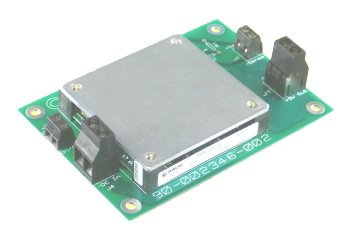
| 36V to 5V 12A DC/DC converter as a half brick regulator module mounted on a circuit board with input and output screw connectors. | ||||||||||||||||||||||||||||||||||||||||||||||||||||||||||||||||||||
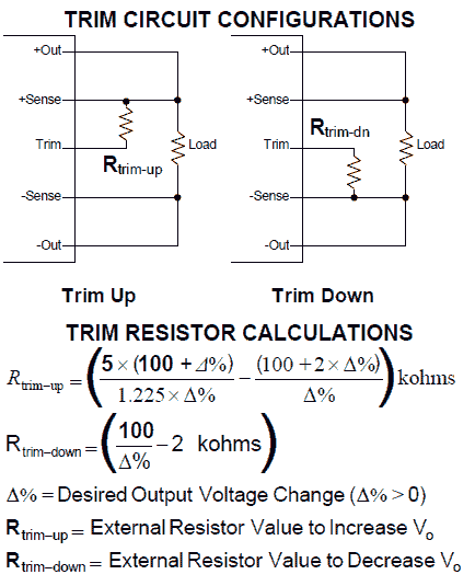
Application Notes: Remote sense and trim functions To use the remote sense, connect the "Sense +" and "Sense -" terminals to wires that go to the load and don't carry any current. This lets the DC converter stabilize the voltage at the load, compensating for voltage loss in the wires that carry current. In other words, without using the "Sense" terminals the voltage will be stabilize at the converter output terminals. As the current flows through wires, connectors, and contacts then resistance of these elements will cause a voltage drop due to Ohm's law. If you run an extra set of wires from the sense terminals to the load that don't carry current, then these can be used to sense the actual voltage at the load and the converter will boost its voltage to compensate for this voltage drop (over a limited range, ±0.5 Volts.) The sense terminals can also be used to trim the voltage with fixed resistors or a pot as follows:  Schematic of how to trim the output voltage. Fixed resistors would also work, they should add to about 10k Ohms. Cooling No heat sink is necessary at ambient temperatures below 30°C. At higher ambient temperatures derate the current or supply a flow of up to 200LFM (linear feet per minute) cooling air is provided (at 100°C ambient). This can be supplied by a 10 cubic feet per minute fan that is about 2.5 inches square. Pentium cooling heat-sink-fan combinations will also do this. Standard heatsinks are available for half-brick modules such as Wakefield 517-95AB, 527-45AB, 527-24AB, 518-95AB, 528-45AB, 528-24AB, or the less expensive CUI VHS-45 or VHS-95. Drawings Gerber files for the circuit board are here DMW75S-05-BoardProductiongerbersandproteusfiles.zip Printed circuit board dimensions are 107mm x 76mm (4.2 x 3.0 inches)  The fully populated board dimensions are 107mm x 76mm x 23mm (4.2 x 3.0 x .9 inches). It includes connectors for Vin and Vout as well as inhibit and Sense terminals. The board mounting holes are 3.6 mm (0.143 inch) in diameter 64mm x 95mm center to center spacing. NOTE! the faceplate temperatures are definitely in the "burn your fingers" category and care should be taken to prevent human contact. |
||||||||||||||||||||||||||||||||||||||||||||||||||||||||||||||||||||
|
|
|
| |||||||||