| August 16, 2023 | |||||||||||||||||||||||||||||||||||||||||||||||||||||||||||||||||||||||||||||||||||||||||||||||||||||||||||||||||||||||||||||||||||
24V DC UPS controller for use in vehicles with 12A pass through |
|||||||||||||||||||||||||||||||||||||||||||||||||||||||||||||||||||||||||||||||||||||||||||||||||||||||||||||||||||||||||||||||||||
  Optional DIN rail mount 24 volt DC UPS module keeps 24 volt equipment alive in vehicles and airplanes using an external sealed lead acid battery and acts as a battery back-up (BBU). Also available in a stand alone enclosure including battery. |
 More battery backups for buses, emergency vehicles and vehicle instrumentation |
||||||||||||||||||||||||||||||||||||||||||||||||||||||||||||||||||||||||||||||||||||||||||||||||||||||||||||||||||||||||||||||||||
 Click here for the 12V 12A car and bus UPS controller |
|||||||||||||||||||||||||||||||||||||||||||||||||||||||||||||||||||||||||||||||||||||||||||||||||||||||||||||||||||||||||||||||||||
This is a 24V DC UPS controller for use in trucks, buses, boats, and wherever a constant supply of 24 volts is needed. It allows equipment in vehicles to continue running when the power is temporarily interrupted by starting motor operation, or when you just need to run under battery backup with up to 12 amps, 290 watts nominal. In addition it controls the charge of the the auxiliary battery at 2 amps. The features are as follows: First it allows you to safely charge an external lead acid battery from the vehicle electrical bus by isolating and current regulating the connection to the auxiliary battery. Second it isolates the extra battery from the vehicle so it won't be discharged by the vehicle electronics, and it won't try to participate in starting the vehicle. Third it powers your equipment in the vehicle using the vehicle electrical system, but switches to external battery power when the vehicle's battery is removed, stolen, or drops below a predetermined voltage. It is not necessary to run an extra sense wire to the ignition, voltage sensing takes care of the decision making. Fourth, it prevents the external battery from being over discharged, keeping it from being damaged. Fifth, it prevents your equipment from running the vehicle's battery down so the vehicle can't be started. In one configuration it cuts off the vehicle's battery when the voltage gets below 26.2 volts, then switches over to the external battery, in other words, it switches over to the auxiliary battery when the engine is shut off and the alternator stops. In another configuration the crossover voltage is lower, say 24 volts. This allows your equipment to run off the vehicle's battery but cut off while the vehicle's main battery still has enough power to safely start the engine. Sixth, it prevents your equipment from losing power, powering down or rebooting while the vehicle is cranking the starting motor. To solve these problems we invented this battery backup (BBU) charging board. The idea is that you can connect the module to the vehicle's electrical bus and it will charge an external 24 volt lead acid battery of your choice. Your equipment, which can be a computer, telemetry equipment, or a vehicle alarm, is connected to the module. This equipment runs off the vehicles's electrical bus until the voltage of the bus drops below a preset voltage, the "N" voltage (from 27 to 18 volts, depending on your needs). Then the external battery takes over. When the external battery drops below the "P" preset voltage (Between 20 volts and 18 volts depending on your requirements) the power is cut off to either prevent damage to the external battery or to run your equipment as long as possible. This uninterruptible power supply control module is specifically designed to withstand the harsh electrical and temperature requirements of automotive equipment including spike, dropouts, load dumps, jump-starting, and high or low temperatures.
Formerly this was called the PST-DC-UPS-2424-12A can be ordered with a range of "N" and "P" values, as explained in the following table.
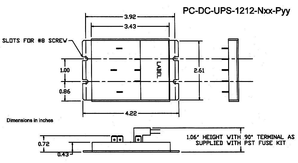
Hook up diagram:  Connection diagram Connection diagram  Dimensions, click on drawing for larger view
DIN rail mounting option (shown here on the 3 amp version of the DC UPS) Questions and Answers 1. Q: My application needs more than 12 amps pass-through current, what can I do? A: A 15 amp version is available, call and let us know your requirements. 2. Q: When the module turns off because both batteries are below their set-points when does the module turn back on? A: The module turns back whenever the main battery or auxiliary battery is greater than their N or P values (this is an improvement over the 3 amp UPS module which turns on only when the vehicle exceeds its N value). 3. Q: What do you have for 12 volt systems? A: Use either the 12 volt 3 amp UPS or 12 volt 12 amp UPS versions 4. Q: What is the recommended fusing? A: If you fuse both the input positive and auxiliary battery positive with a 15 amp fast blow fuse the module will be protected from reverse polarity and short circuit conditions. In addition, if the load can source current it should have a 15 amp fast acting fuse as well. 5. Q: I am charging a very small battery with this, the 850 mA charge rate is too high according to the battery manufacturer. A. The charge algorithm used is kind to the batteries even when the maximum charge rate is over the C/3 rate specified by the battery manufacturers. For more information click on this link. |
|||||||||||||||||||||||||||||||||||||||||||||||||||||||||||||||||||||||||||||||||||||||||||||||||||||||||||||||||||||||||||||||||||
|
|
|
| |||||||||